

Eliminate All Single Points Of Failure With Triple Modular Redundancy
The weakest component/subsystem dictates the reliability of a series system, and with LayerZero Triple Modular Redundancy (TMR), you can be assured that there are no single points of failure. Designed for applications that demand the highest reliability, LayerZero TMR eliminates all single points of failure by providing isolated, redundant control paths for all communications.
The Triple Modular Redundant, eSTS has been designed in a manner suitable for application in the most demanding of mission-critical environments. TMR consists of three independent control systems and a voter, where two of three votes win. Reliability is increased between one to two orders of magnitude.
This system architecture is fifty years old and has been designed to withstand failures in the data acquisition, failures in the system control board , failures in the gate drive, and failures in the front board & peripherals. In the event of one of these failures, the unit sends an alarm and continues to make emergency transfers.
Triple Modular Redundancy, a proper noun, is a based on proven statistics and stringent mathematics. There are similar sounding terms like, tri- or triple- redundant, used in industry to describe other STS products – but they simply do not yield the same, high level of reliability. Below are two interactive presentations designed to help users understand the benefits of Triple Modular Redundancy.
Triple Modular Redundancy Basics
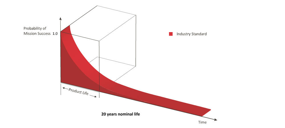
• Systems have a finite life expectancy. In mission critical systems, the requirement for the probability of mission success is virtually 100%.
• Unfortunately, industry standard static transfer switch systems are not designed to meet this criteria.
"Industry Standard"
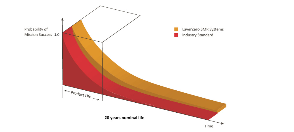
LayerZero’s Single Module Redundant (SMR) STS improves the probability of mission success vastly with:
• Elimination of all single points of failure
• Redundancy of power supplies
• Segmentation of gate drives by Source and Phase
• Use of fiber optics to eliminate errors due to conducted & radiated noise
• The LayerZero SMR STS is well-suited for STS based dual cord distribution systems.
LayerZero SMR Systems
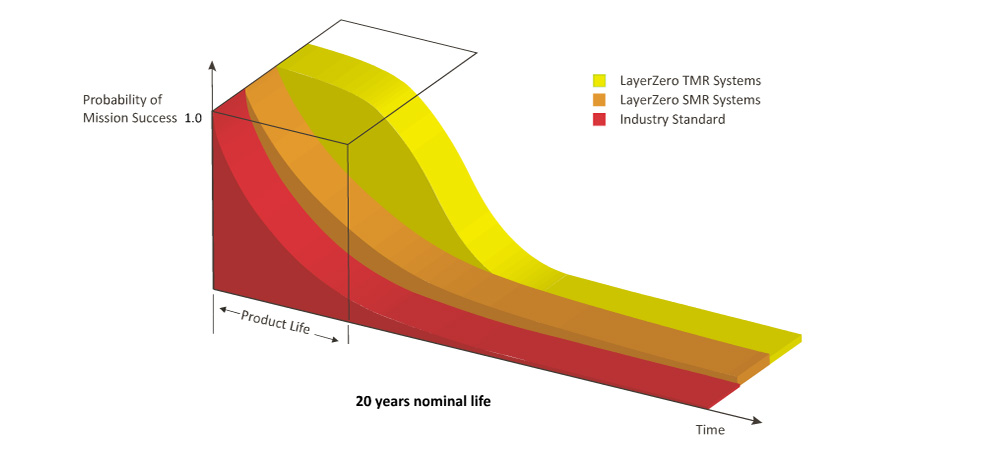
Triple Modular Redundant Systems increase the probability of mission success by an order of magnitude during the operational life of the STS. TMR systems are deployed with:
• Three observers
• Three controllers
• Three actuators (gate drives) for each pair of SCRs
• Redundant power, optical fiber
The STS is designed to continue to meet specification in the event of a catastrophic failure of one of the observer or controller or drive or power supply systems.
LayerZero TMR Systems
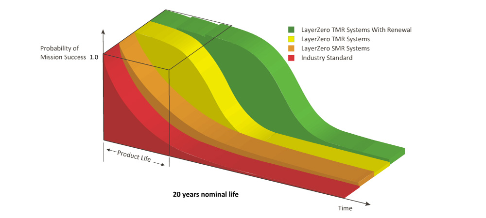
With appropriate and timely service and maintenance the TMR System can be Renewed to maintain virtually 100% probability of mission success. Triple Modular Redundancy is a proven topology in various life safety and mission critical systems across the industrial landscape. LayerZero is the only provider of the benefits of TMR in power distribution systems. TMR STS are ideally suited when reliability simply cannot be compromised in single cord or dual cord power systems.
LayerZero TMR Systems with Renewal
Triple Modular Redundancy, a proper noun, is a based on proven statistics and stringent mathematics. There are similar sounding terms like, tri- or triple- redundant, used in industry to describe other STS products – but they simply do not yield the same, high level of reliability. The underlying mathematics of TMR is explained elsewhere on this page under Reliability/System/Triple Modular Redundancy/The Mathematics.
Triple Modular Redundancy - The Mathematics
Overall Thought Process:
• The probability of mission success of a single system is not always sufficient to meet design objectives.
• Redundant architecture provide a design method for improving the probability of mission success beyond limits practical for single systems.
• Redundant architectures are continuously evolving and creating new design options for the creators of mission critical environments to evaluate.
Triple Modular Redundancy Overview:
• Brief tutorial on the definitions of probability.
• Review the concept of probability of mission success and test the probability of mission success for non-redundant systems.
• Introduce redundancy as a method of improving system performance.
• Present, analyze and compare both well known and new redundant system architectures.
Brief Tutorial on the Definitions of Probability
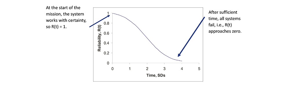
• A mission critical system must operate without failure for a finite time T, where T is the duration of the mission.
• When a system runs, it is realizing a chance experiment, where the time of failure is represented by a random variable, t.
• In the case of mission critical systems, the set of outcomes {t≤t} are the outcomes where the system, that operated at time t = 0, fails at or before time t.
How Do We Quantify Reliability?
• Reliability, R(t), is a distribution function, R(t) = 1 –P{t≤t}, a function that describes the probability of a system operating at time t.
Linking Reliability to Hazard Rate
• Hazard rate h(t) is the instantaneous failure rate of a system having survived to time t.
• Typical units are FIT, or failures per 109 hours.
• Base data from handbooks and experimental results usually takes the form of hazard rate.
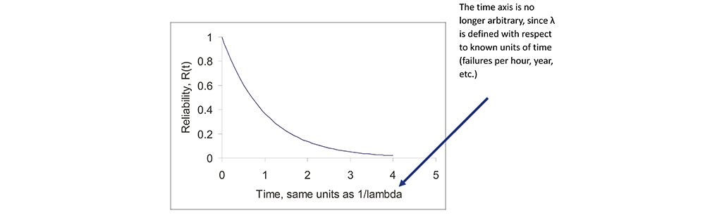
Reliability for a Constant Hazard Rate
• When hazard rate, h(t) = λ is constant, R(t) = e-λt, the negative exponential probability distribution function, the simplest (and most widely used) distribution function.
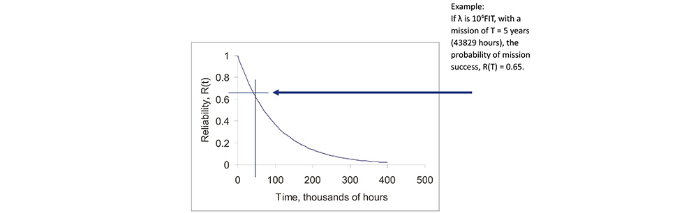
Probability of Mission Success for Constant Hazard Rate
• The probability of mission success (POMS), for a mission of time T, is then R(T) = e-λT.
Linking Reliability to MTBF
• Mean Time Between Failure (MTBF) is defined as a function of the reliability distribution function,
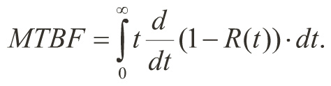
• From above, when h(t) = λis a constant, R(t) = e-λt, and MTBF is then 1/λ.
• This simple relationship between λand MTBF makes MTBF an easy to calculate and popular metric of anticipated system performance.
To the Test –Expected Performance of Single Systems
• In any test case, basic parameters must be defined:
• T = the duration of the mission,
• λ= 1/MTBF, the hazard rate of the system.
• R(t), the reliability of the entire system as a function of λ.
• Parameters can be varied to test the system’s reaction to changes.
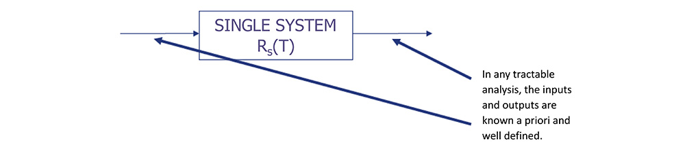
Single System Performance
• Assume a five year mission, T = 5 yr, for a single system, where R(t) = e-λt.
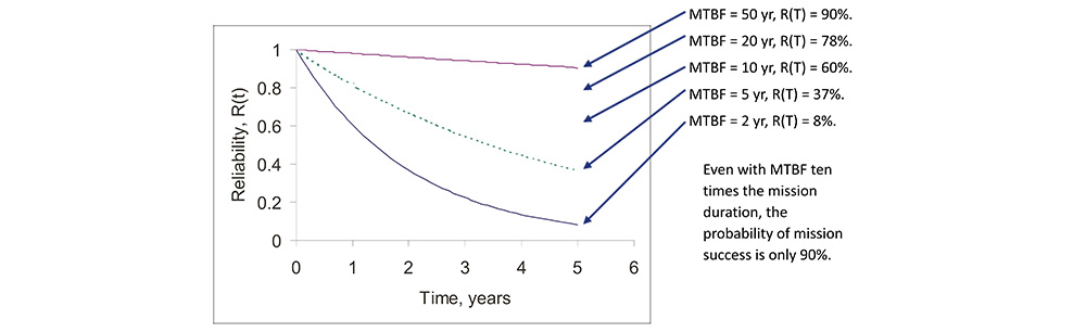
The Point of Diminishing Returns
• The point of diminishing returns for increasing MTBF comes quickly, since exponential increase in MTBF yields rapidly decreasing improvement in POMS.
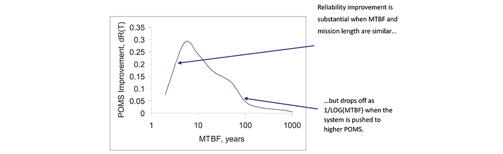
Where Do We Go For Further Improvement?
• Improving the reliability of a single system can be accomplished by using fewer sub-systems (cleverness/innovation) or higher quality subsystems (money).
• If MTBF is roughly proportional to required investment, improving POMS beyond 80% increments POMS with 1/LOG(investment).
• This is a battle that won’t be won.
• When the target POMS is greater than 90% to 98%, the system cost becomes so high that multiple systems, each having POMS less than the target, may be purchased for less net investment than the single system.
• The architecture of configuring a multiplicity of systems to achieve POMS greater than that of the constituents results in a redundant system.
Modes of Redundant System Operation
Static Redundancy
• Also known as masking redundancy.
• SR systems utilize multiple single systems to instantaneously mask failures.
• All single systems operate at all times.
Dynamic Redundancy
• DR systems utilize multiple single systems, where single system outputs are switched in the event of a failure.
• Not all single systems operate at all times.
Static Redundancy Architectures
Triple Modular Redundancy is the most popular static redundant architecture for large, complex systems.
• TMR scales perfectly and is completely general in applicability.
• TMR yields Byzantine Resilient systems.
Error Checking and Correcting Redundancy is popular for small, highly repetitive systems.
• ECC offers improved POMS with little extra investment.
• ECC does not usually yield Byzantine Resilient systems.
Byzantine Resilience is the property where a system tolerates ALL possible failure modes, not just a set of likely failure modes.
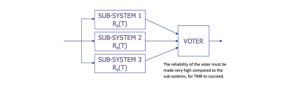
Triple Modular Redundant Architecture
• TMR consists of three independent systems, where each system receives the same inputs.
• Each system’s output feeds a voter, where two of three votes win.
To the Test – TMR Improvement Over a Single System
• The reliability of a TMR system is the probability of all three modules operating plus the probability of any two modules operating,
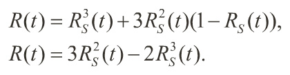
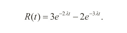
When RS(t) = e-λt, from constant hazard rate systems, the net POMS becomes,
Reliability Improvement Via TMR
• TMR systems improve reliability dramatically over simplex systems with equivalent sub-system reliability.

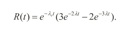
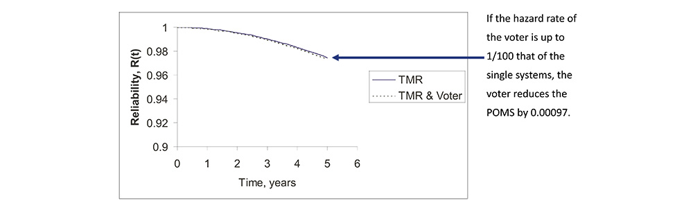
The Effect of Voter Reliability
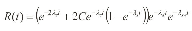
• If the voter exhibits a hazard rate λv, then the reliability of a TMR system becomes
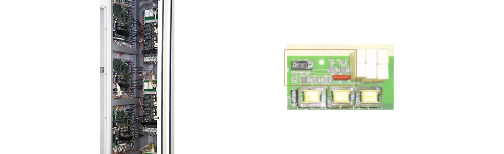
What Does a TMR Control System and Voter Look Like?
• Three separate, independent control systems, with a simple, highly reliable voter.
Error Checking and Correcting Redundant Architecture
• ECC requires that the system process additional information along with the basic data associated with its operation.
• Two identical check generators, a syndrome detector & decoder and a corrector are located around the system.

To the Test –ECC Improvement Over a Single System
• Robustness of an ECC redundant system is strongly dependent on the amount of extra information processed and the strength of the check generating functions.
This test is based on the following parameters:
• The additional ECC subsystems have hazard rate λs/100.
Capacity is expanded to 3x single system.
• The POMS for an system with ECC is the reliability of the checking and correcting sub-systems, multiplied by the reliability of the system with “perfect" ECC
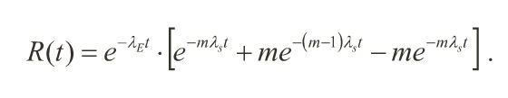
λE is the hazard rate of the ECC subsystems,
λs is the hazard rate of the single system,
m is the number of systems used.
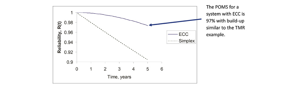
Reliability Improvement Via ECC
• ECC systems can provide POMS similar to TMR.
• The major advantage of ECC applies when many small systems operate in parallel and share one ECC subsystem, e.g., memory chips.
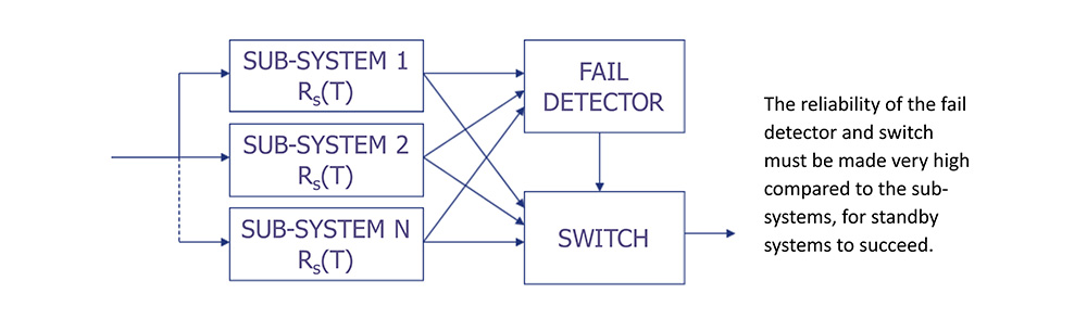
Dynamic Redundancy Architectures
• Hot standby and cold standby redundancy are the standard implementations of dynamic redundant architectures.
• Standby redundancy requires a fault detecting means to determine when an active system has faulted.
• Standby redundancy also requires a switching sub-system to select against faulted systems.
• Duplex redundancy is a form of hot standby that includes reconfiguration to remove the detecting and switching means from the system after a faulted system is taken off line.
• Duplex redundancy seeks to improve the reliability of basic hot and cold standby architectures to that of a single system after addressing a fault.
• Duplex redundancy is a recent architectural concept.
Hot and Cold Standby Redundancy
• Hot standby and cold standby are often used for physical plant systems.
• Hot standby spares have the advantage that performance can be ascertained under normal running conditions, whereas cold standby spares are normally more economical.
Examples of Standby Redundancy
Cold standby – Backup generator with automatic transfer switch.
• Generator does not run continuously.
• When utility power is lost, the generator starts.
• Once the generator is running and stable, the load is switched to the generator.
Hot standby – Isolated redundant UPS system.
• Both UPS units run continuously.
• Load is shared between UPS units, each UPS running at less than 50% capacity.
• When one UPS fails, solid state transfer switches consolidate the load on the remaining UPS.
To the Test – Duplex Redundant Improvement Over Single System
• All dynamic redundant architectures are strongly affected by the reliability of the fault detection and switching sub-systems.
• It is possible to embed static redundant components within a dynamic redundant system to achieve highly reliable fault detection and switching.
This test is based on the following parameters:
• Both the detecting and switching subsystems have hazard rate λs/10.
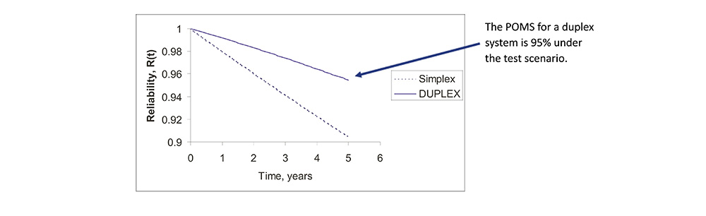
• The coverage factor C, the probability of successful reconfiguration to remove the detecting and switching subsystems, is 0.9.
Reliability Improvement Via Duplex Redundancy
• Duplex redundancy yields improved POMS over single systems, but not a high as static redundant architectures.
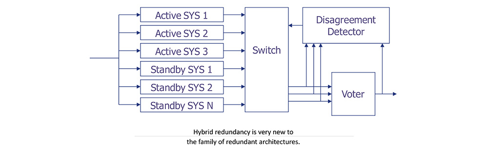
Hybrid Redundant Architecture
• Hybrid redundancy seeks to combine the strengths of both static and dynamic redundancy.
• HR systems operate as TMR systems until one module fails.
• Once a failed module is detected by disagreement, a standby module replaced the module that disagrees.
To the Test – Hybrid Redundancy Improvement Over Single System
• All dynamic redundant architectures are strongly affected by the reliability of the fault detection and switching sub-systems.
• It is possible to embed static redundant componentswithin a dynamic redundant system to achieve highly reliable fault detection and switching.
This test is based on the following parameters:
• Both the detecting and switching subsystems have hazard rate λs/10.
• The coverage factor C, the probability of successful reconfiguration to remove the detecting and switching subsystems, is 0.9.
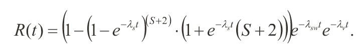
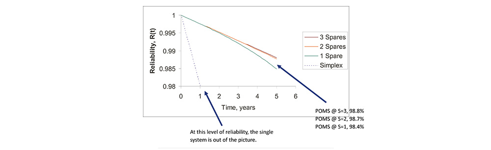
Reliability Improvement Via Hybrid Redundancy
• HR system exhibits very high POMS compared to single system.
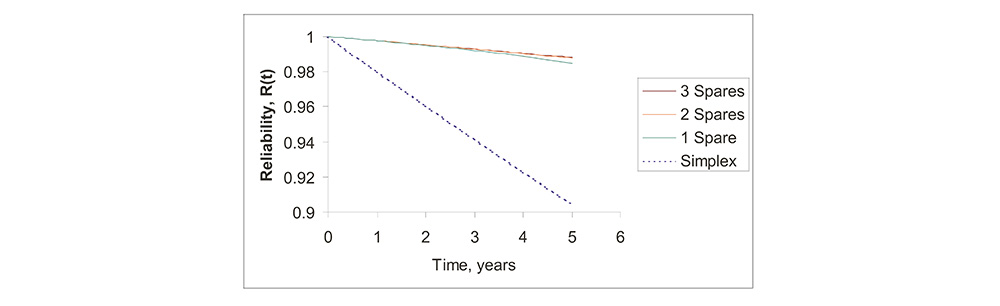
Hybrid Redundancy Has A Point of Diminishing Returns
• Beyond two spares, there is little improvement in POMS.
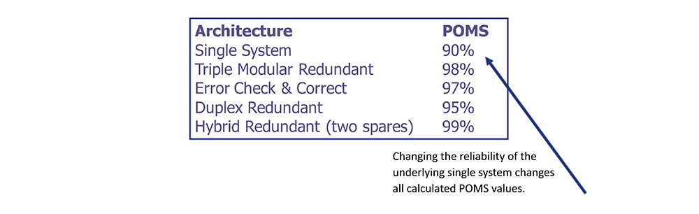
Redundant Architectures Compared
• For the common case used in the tests, these are the results for probability of mission success.
Reliability Improvement Factor
• The reliability improvement factor (RIF) is defined as the ratio of the probability of single system failure to that of the redundant system.

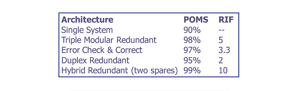
The Leverage of Redundant Systems
• Redundant architectures provide leverage, where the RIF exceeds the relative investment required to achieve the reliability improvement.
• In this case, leverage is defined as the ratio of RIF to relative investment.
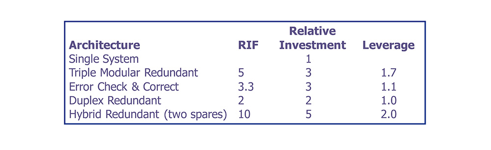
Designers have a spectrum of RIF and investment options on which to base design choices.
Summary and Conclusions
• A mission critical system is one that must operate for a prescribed mission of finite duration without failure.
• Reliability is described as a probability distribution function.
• Hazard rate h(t) is the instantaneous failure rate of a system having survived to time t.
• When hazard rate is considered to be constant λ,
• MTBF becomes 1/λ, and
• Reliability becomes the negative exponential function.
• The probability of mission success is the reliability evaluated at the duration of the mission.
• When the MTBF of the system becomes long with respect to the length of the mission, increasing the MTBF of the system yields very small improvements in probability of mission success.
• When the POMS of a single system is not high enough to satisfy design requirements and the point of diminishing returns has been reached, redundant architectures allow further reliability improvement.
• Static redundant architectures mask faults as they occur.
• Dynamic redundant architectures eliminate faults by switching in spares.
• Hybrid redundant architecture yields probability of mission success exceeding that obtainable from either static or dynamic architectures alone.
• Redundant architectures yield leverage, returning more reliability improvement than required investment.